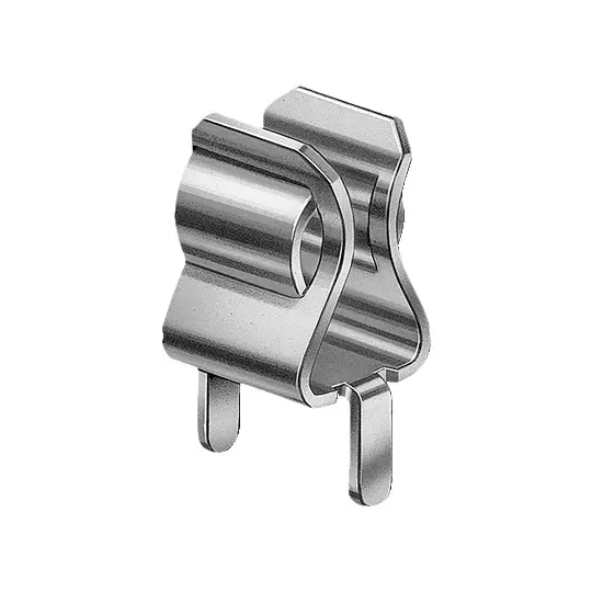












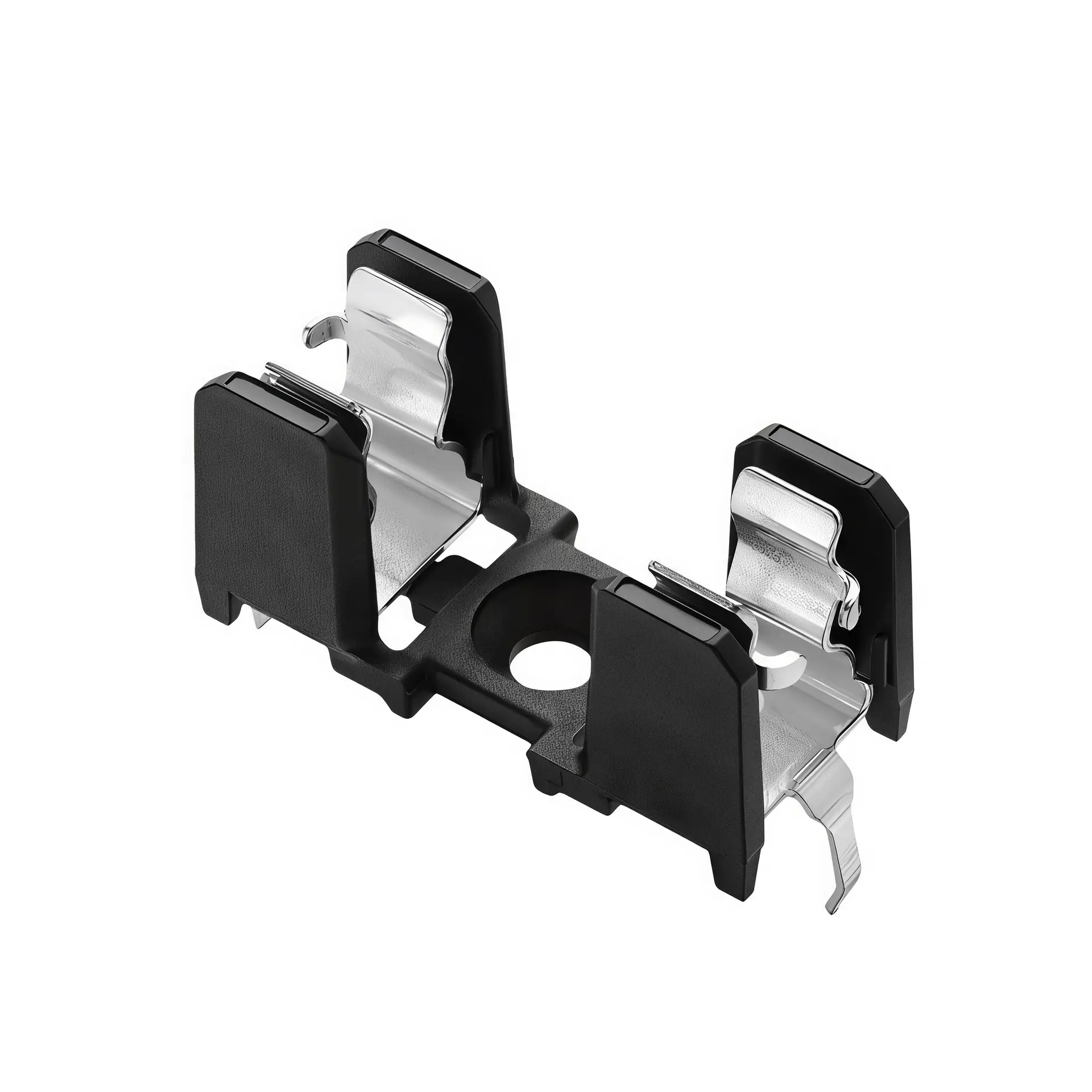
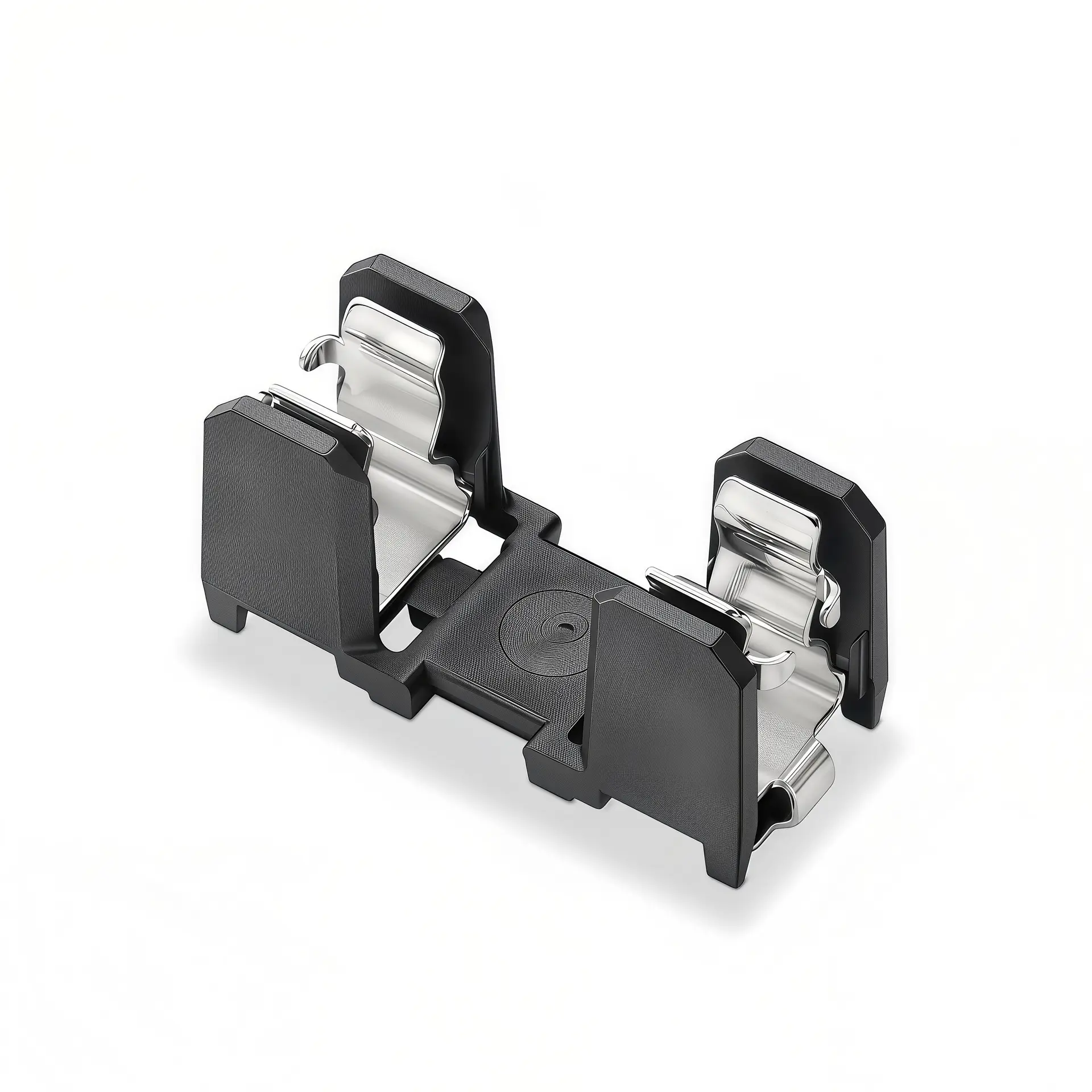


PTF/15S pcb mount fuse holder for 5x20mm Fuse Clip
Dimension Drawing


Portafusibles para montaje en PCB for 5.2x20mm cartridge fuses is reinforced through‑hole soldered high‑current circuit‑protection component for industrial PCBA. This fuse block adopts glass‑fiber reinforced PBT+GF30 base with PC upper cover, both UL94 V0 flame‑retardant grade, paired with durable tin‑copper alloy terminals. Specially optimized for wave‑soldering process, withstand short‑time high soldering temperature of 230‑240℃ for 3 seconds. Wide operating temperature covers‑40 ℃ to +130 ℃, well‑suited for harsh industrial PCB environment. Widely applied in high‑power power supplies, industrial control boards, power conversion equipment and general‑purpose electronic PCBA.
Características principales del producto
- Compatible with standard 5.2 × 20 mm glass / ceramic tubular cartridge fuses for high‑current PCB‑level circuit‑protection
- Electrical rating:16A, 500V(250V) AC, delivers stable high‑current carrying performance for industrial PCB circuits
- Reinforced insulating housing: Base PBT+GF30, upper cover PC, UL94 V0 flame‑retardant grade, enhanced mechanical strength and heat‑resistance
- Tin‑copper alloy terminals, good conductivity and anti‑oxidation for long‑term reliable conduction
- Special wave‑soldering resistance: withstand soldering temperature 230‑240℃ for 3 seconds, fits mass‑production SMT / wave‑soldering workflows
- Wide operating temperature‑40 ℃ ~ +130 ℃, adapts to low‑temperature and high‑temperature industrial working conditions
- Insulation resistance>100 MΩ(500VDC, 1min); DC withstand voltage up to1500V DC for enhanced dielectric safety
- Through‑hole PCB soldering mounting design, standard pin‑footprint for printed‑circuit‑board layout
- RoHS‑compliant construction, meets global industrial‑electronics environmental‑protection requirements
Different from ordinary unreinforced plastic PCB fuse holders, this PBT+GF30 glass‑fiber reinforced base improves mechanical strength and thermal deformation resistance. Optimized solder‑resistance property avoids housing melting/deformation during wave‑soldering mass‑production, it is preferred solution for high‑current industrial power‑supply PCBA projects.
Especificaciones técnicas completas
| Elemento de especificación | Valor del parámetro |
|---|---|
| Modelo | PTF(15S) |
| Fusible compatible | 5.2 × 20 mm glass / ceramic tubular cartridge fuse |
| Corriente nominal | 16A |
| Tensión nominal | 500V(250V) AC |
| Material de vivienda | Base:PBT+GF30; Upper cover:PC, UL94 V0 flame‑retardant |
| Material terminal | Tin‑copper alloy |
| Soldering Resistance | 230‑240℃ for 3 seconds |
| Rango de temperatura de funcionamiento | ‑40 ℃ ~ +130 ℃ |
| Resistencia de aislamiento | >10 MΩ (500 VDC, 1 min) |
| Voltaje de resistencia | 1500 V CC |
| Método de montaje | Montaje para soldadura de PCB de orificio pasante |
Note: Original datasheet does not provide contact resistance parameter.
Guía de selección y solicitud
When selecting this reinforced PCB‑mount fuse holder for 5.2×20 mm fuses, confirm fuse dimension, system AC voltage and continuous operating‑current first. Select matching‑rating 5.2x20mm tubular fuses and reserve a 1.25‑1.5× safety margin to avoid over‑heating under continuous‑load. For wave‑soldering mass‑production PCBA, strictly control soldering temperature & dwell‑time within 230‑240℃ /3s specification to prevent housing damage. This wide‑temp variant fits equipment working in low‑temperature or high‑temperature ambient environment. Follow official PCB dimension drawing for pad layout to guarantee soldering reliability and stable electrical performance.
Escenarios de aplicación típicos
- High‑power switching power supplies and industrial power‑supply PCBA circuits
- Industrial control boards and automation equipment control‑circuit boards
- Power converter modules and energy‑storage auxiliary‑circuit boards
- Test instruments and high‑power laboratory power‑supply PCB
- Communication equipment high‑current power‑input protection circuits
- Medium‑power LED power‑drivers and industrial lighting control PCBA
Instrucciones de instalación y mantenimiento
1. Select correct‑rating 5.2 × 20 mm glass / ceramic tubular cartridge fuse according to circuit‑protection requirements.
2. Design PCB through‑hole pads strictly follow official dimension drawing to ensure soldering compatibility.
3. Complete wave‑soldering or manual‑soldering; strictly keep soldering condition within 230‑240℃ for max 3 seconds to avoid plastic housing thermal‑damage.
4. Inserte el fusible tubular completamente en la cavidad del portafusibles para un contacto eléctrico fiable.
5. No opere más allá de los límites de voltaje y corriente nominales publicados para evitar fallas en el aislamiento y riesgos para la seguridad.
6. Cut‑off full power supply and discharge circuit before fuse replacement to prevent electric‑shock hazard.
7. Periodically inspect for loose fuse, terminal oxidation or heating signs; replace components promptly when anomalies are found.
Preguntas frecuentes
Q1: What fuse size fits this pcb fuse holder?
A1: It fits standard 5.2 × 20 mm glass and ceramic tubular cartridge fuses for high‑current industrial PCB‑level over‑current‑protection.
P2: ¿Cuáles son sus características eléctricas?
A2: Rated 16A, 500V(250V) AC; 1500V DC withstand voltage, insulation resistance>10 MΩ under 500VDC 1‑min test condition.
Q3: What is housing material feature?
A3: Base adopts glass‑fiber‑reinforced PBT+GF30, upper cover PC material, both UL94 V0 flame‑retardant grade for improved mechanical and thermal‑resistance performance.
Q4: What is soldering‑resistance and temperature range?
A4: Withstands soldering temperature of 230‑240℃ for 3 seconds; operating temperature‑40 ℃ ~ +130 ℃ for wide‑range industrial environment.
Q5: What terminal material is used?
A5: Tin‑copper alloy terminals with good conductivity and anti‑oxidation for long‑term high‑current carrying.
Q6: What mounting style and typical‑applications?
A6: Through‑hole PCB soldering mount; mainly for high‑power power‑supply, industrial control board, power converter and other industrial PCBA over‑current‑protection.