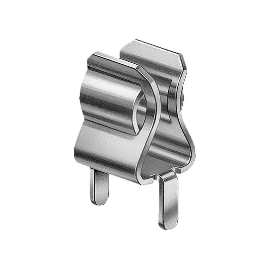













PCB mount fuse holder for 5.2x20mm tubular fuses is a through‑hole soldered circuit‑protection component for low‑voltage electronic PCBA. This fuse base uses PBT or PA UL94 V0 flame‑retardant housing paired with durable H65 brass terminals, delivering low contact resistance and reliable insulation performance for both AC and DC circuits. Through‑hole PCB mounting supports standard automated soldering processes; green and black housing colors are available upon custom request. Widely used in household appliances, test instruments, adapters and general‑purpose electronic control boards.
Core Product Features
- Compatible with standard 5.2 × 20 mm glass / ceramic tubular cartridge fuses for low‑voltage electronic equipment protection
- Electrical rating: 0.1‑6.3A, 125V / 250V AC/DC; well‑suited for small‑to‑medium‑current PCB circuits
- Housing material: PBT / PA, UL94 V0 flame‑retardant grade; good heat‑resistance and dielectric performance
- Terminal material: 0.4 mm / 0.5 mm thickness H65 brass, stable spring clamping performance
- Contact resistance below 5 mΩ; insulation resistance greater than 100 MΩ; 3000V AC power‑frequency withstand voltage for safe PCB‑side operation
- Through‑hole PCB soldering mounting design, fits conventional SMT / wave soldering production workflows
- Standard green / black housing; custom colors are acceptable according to project requirements
- RoHS‑compliant construction, satisfies global consumer‑electronics safety and environmental‑protection standards
Different from panel‑mount fuse holders, this through‑hole PCB‑mount variant saves cabinet space and allows fuse replacement directly on printed circuit boards. Dual‑option PBT/PA housing material and customizable colors provide high flexibility for appliance and instrument design projects.
Full Technical Specifications
| Specification Item | Parameter Value |
|---|---|
| Model | PTF‑77 |
| Compatible Fuse | 5.2 × 20 mm glass / ceramic tubular cartridge fuse |
| Rated Current Range | 0.1A‑6.3A |
| Rated Voltage | 125V / 250V AC / DC |
| Housing Material | PBT / PA, UL94 V0 flame‑retardant |
| Terminal Material | 0.4 mm / 0.5 mm H65 brass |
| Contact Resistance | < 5 mΩ |
| Insulation Resistance | > 100 MΩ |
| Power Frequency Withstand Voltage | 3000V AC |
| Available Housing Color | Green, Black (custom colors on request) |
| Mounting Method | Through‑hole PCB soldering mount |
Selection & Application Guidance
When selecting this 5.2×20 mm PCB mount fuse holder, confirm fuse dimension, system AC‑DC voltage and operating current range first. Choose matching‑rating 5.2x20mm tubular fuses and reserve a 1.25‑1.5× safety margin to avoid over‑heating under continuous load. Select PBT or PA housing material according to PCB board ambient temperature requirements; green or black standard colors are available with custom‑color support for product appearance matching. Follow official PCB dimension drawing for pad layout, ensure proper through‑hole soldering quality to guarantee stable current‑carrying performance.
Typical Application Scenarios
- Household appliance control PCB and consumer‑electronics circuits
- Power adapters, small switching power supplies and power‑supply boards
- Test instruments, multimeters and laboratory small‑power circuit boards
- Communication equipment and network‑device auxiliary protection circuits
- LED drivers and low‑power lighting‑control PCBA
- Industrial small‑automation modules and low‑voltage control boards
Installation & Maintenance Instructions
1. Select correct‑rating 5.2 × 20 mm glass / ceramic tubular cartridge fuse for your circuit‑protection requirements.
2. Design PCB through‑hole pads strictly per official dimension drawing to ensure soldering compatibility.
3. Complete wave‑soldering or hand‑soldering with appropriate temperature and dwell time; avoid over‑heat damage to plastic housing.
4. Insert tubular fuse fully into holder cavity for reliable electrical contact.
5. Do not operate beyond published rated voltage‑current limits to prevent insulation breakdown and safety hazards.
6. Cut off power supply and discharge circuit before fuse replacement to prevent electric‑shock risk.
7. Periodically check for loose fuse, contact oxidation or heating; replace components promptly when anomalies appear.
Download 5.2x20mm PCB Mount Fuse Holder Datasheet (PDF)
Frequently Asked Questions
Q1: What fuse size fits this PCB mount fuse holder?
A1: It accepts standard 5.2 × 20 mm glass and ceramic tubular cartridge fuses, widely‑used for consumer‑electronics PCB‑level over‑current‑protection.
Q2: What are the electrical ratings?
A2: Rated current range 0.1‑6.3A; rated voltage 125V /250V for both AC and DC, for small‑to‑medium‑current low‑voltage PCB circuits.
Q3: What housing material options are available?
A3: PBT or PA housing with UL94 V0 flame‑retardant grade, green and black as standard colors, custom colors acceptable upon request.
Q4: What are terminal specifications?
A4: Terminals are made of 0.4 mm /0.5 mm‑thick H65 brass; contact resistance <5 mΩ for stable long‑term conduction.
Q5: What are insulation and withstand‑voltage parameters?
A5: Contact resistance <5 mΩ, insulation resistance>100 MΩ, power‑frequency withstand voltage 3000V AC for reliable PCB‑side insulation safety.
Q6: What mounting style does it adopt?
A6: Through‑hole PCB soldering mount, compatible with wave‑soldering and manual soldering for printed circuit boards.
Q7: What are main application‑fields?
A7: Applied for household appliances, power adapters, test instruments, LED drivers, communication equipment and various low‑voltage PCB‑based over‑current‑protection circuits.